The moment of inertia is a fundamental concept in physics that describes the resistance of an object to changes in its rotational motion. It is a measure of the distribution of mass within an object and is crucial in understanding the behavior of rotating systems. One of the simplest and most instructive examples of calculating the moment of inertia is that of a rod. The moment of inertia of a rod is a basic problem in mechanics that is often encountered in introductory physics courses. In this article, we will delve into the calculation of the moment of inertia of a rod, exploring the underlying physics, the mathematical derivations, and the practical implications of this concept.
Introduction to Moment of Inertia

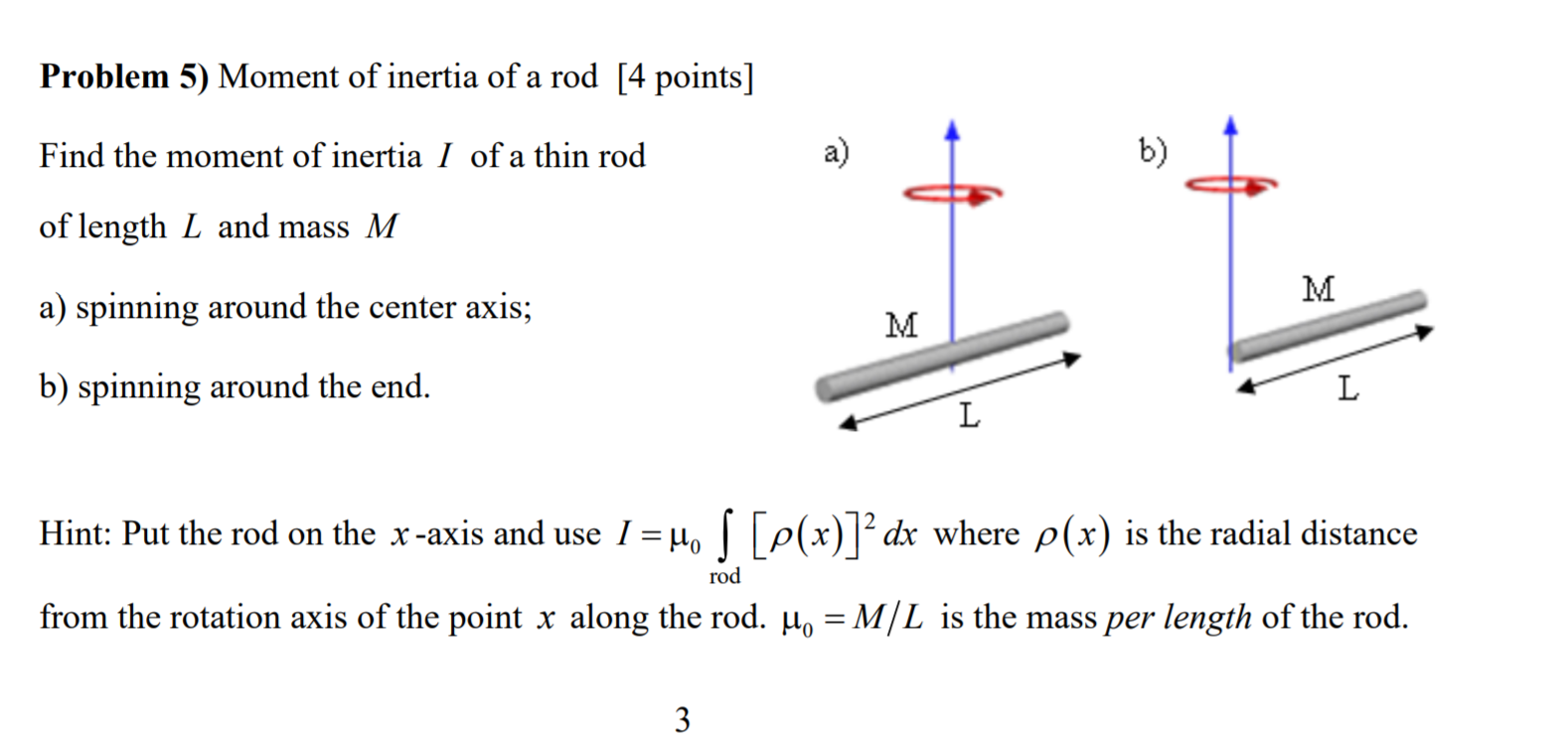
The moment of inertia, denoted by the symbol I, depends on the mass distribution of the object and the axis around which it rotates. For a rod, the moment of inertia can be calculated using different methods depending on the axis of rotation. The most common axes considered are the axis passing through the center of the rod and perpendicular to its length (often referred to as the “center axis”) and the axis passing through one end of the rod and perpendicular to its length (referred to as the “end axis”). Understanding the moment of inertia around these axes is essential for predicting the rotational dynamics of the rod.
Derivation of Moment of Inertia for a Rod
To derive the moment of inertia of a rod, we consider it as being made up of many small, infinitesimal pieces of mass. The moment of inertia of each piece is considered, and then these contributions are summed (or integrated) over the entire rod. For a rod of mass M and length L, rotating around its center axis, the moment of inertia (I) can be derived using the following formula:
I = ∫r^2 dm, where r is the distance from the axis of rotation to the infinitesimal mass element dm.
Assuming the rod has a uniform mass distribution, the mass per unit length (μ) is given by μ = M/L. For a small element of length dx at a distance x from one end of the rod, the mass of this element is dm = μdx. When rotating around the center axis, the distance of this element from the axis is x - L/2. Thus, the moment of inertia around the center axis can be calculated by integrating over the length of the rod.
| Axis of Rotation | Moment of Inertia Formula |
|---|---|
| Center Axis | I = (1/12)ML^2 |
| End Axis | I = (1/3)ML^2 |

Practical Applications and Considerations

The calculation of the moment of inertia of a rod has numerous practical applications in engineering and physics. It is essential for designing and analyzing rotational systems, such as gyroscopes, flywheels, and rotating machinery. Understanding the moment of inertia helps in predicting how these systems will behave under different conditions, including the energy required to start or stop rotation, the stability of the system, and the stresses and strains experienced by the components.
Technical Specifications and Comparisons
When comparing the moments of inertia of rods of different lengths and masses, it becomes apparent that both factors significantly influence the rotational dynamics. A longer rod has a larger moment of inertia around its center axis than a shorter rod of the same mass, due to the increased distance of the mass elements from the axis of rotation. Similarly, a rod with a larger mass per unit length will have a greater moment of inertia than a less massive rod of the same length. These considerations are crucial in the design of systems where rotational motion plays a key role.
Key Points
- The moment of inertia of a rod depends on its mass distribution and the axis of rotation.
- For a uniform rod, the moment of inertia around the center axis is given by I = (1/12)ML^2, and around the end axis by I = (1/3)ML^2.
- The parallel axis theorem is a useful tool for calculating the moment of inertia around different axes.
- Understanding the moment of inertia is crucial for designing and analyzing rotational systems.
- The length and mass of a rod significantly influence its moment of inertia and subsequent rotational behavior.
In conclusion, the moment of inertia of a rod is a fundamental concept that underpins our understanding of rotational motion. By grasping the principles behind its calculation and the factors that influence it, we can better design, predict, and control the behavior of rotational systems. Whether in the context of a simple rod or complex machinery, the moment of inertia plays a pivotal role in mechanical engineering and physics, making it an essential topic for study and application.
What is the moment of inertia, and why is it important?
+The moment of inertia is a measure of an object’s resistance to changes in its rotation. It is important because it helps predict the behavior of rotating systems, including the energy required for rotation and the stability of the system.
How does the axis of rotation affect the moment of inertia of a rod?
+The axis of rotation significantly affects the moment of inertia. For a rod, rotating around its center axis yields a different moment of inertia than rotating around an end axis, due to the differing distances of the mass elements from the axis of rotation.
What is the parallel axis theorem, and how is it used?
+The parallel axis theorem states that the moment of inertia about any axis parallel to the axis through the center of mass is equal to the moment of inertia about the center of mass axis plus the product of the mass of the body and the square of the distance between the two axes. It is used to calculate the moment of inertia around different axes.